Project Development
- Aminur _
- Feb 16, 2023
- 2 min read

Updated: Feb 19, 2023
Welcome back to one of the best blog sites in SP DCHE. Before I get started on anything, this blog will be my last one. However, don't fret or worry as I plan on upgrading this site to include my past projects and events I've participated in in the past rather than just focusing on one module. In today's blog, I'll be covering the entire design and development of a CO Detection System my teammates and I have been working on for the past few months.
Describe My Team's Chemical Device
What are we making?
Why are we making it?
Research
Team Planning, Allocation, and Execution
Planning Stage
Role Allocation
Project Execution
Morphological Chart
Concept Sketches
Concept Evaluation Matrix
Triz
Revised Concept
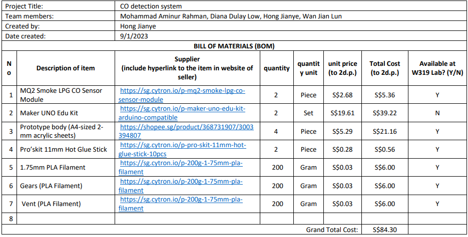
BOM
Gannt chart
design and build processes
Cardboard Prototyping
Arduino Coding
Cardboard prototype working video
Fusion 360
3D-Printing
Laser Cutting
Assembling Final Prototype
Final prototype working video
Describe problems encountered and how the team solved them.
Wires getting tangled
Fusion format for laser cutting
3D printing errors which led to components not fitting
Acrylic glueing
Project design files as downloadable files.
Learning reflection
1. Describing My Team's Chemical Device
a. What are we making?
A Carbon Monoxide Detection system
b. Why are we making it?
There was recently an incident at Ali Redza's car repair shop where one of his employees fainted all of a sudden when operating on a car engine. After further investigation, Redza discovered that the cause of this could've been because of incomplete conbustion of fuel in the car engine which produced significant amounts of carbon monoxide.
Hence Ali Redza has tasked us to conduct research and find a sutable solution for this problem so that it doesn't happen again for his other employees.
c. Research
Carbon Monoxide (CO) is measured in “Parts per Million” (PPM). The information below illustrates what symptoms may appear after one hour of exposure to CO:
0-9 ppm CO: No health risk; normal CO levels in air.
10-29 ppm CO: Problems over long-term exposure; chronic problems such as headaches, nausea
30-35 ppm CO: Flu-like symptoms begin to develop, especially among the young and the elderly.
36-99 ppm CO: Flu-like symptoms among all; nausea, headaches, fatigue or drowsiness, vomiting.
100+ ppm CO: Severe symptoms; confusion, intense headaches; ultimately brain damage, coma, and/or death, especially at levels 300-400+ ppm
According to Occupational Safety and Health Administration (OSHA), 50ppm for 8hrs of exposure is permissible. However, Redza's employees work very hard and are capable of working 12 hour shifts with no issues. Hence we concluded that our CO Detection System should keep the CO levels under 20ppm so that his workers will be capable of working 24/7
2. Team Planning, Allocation, and Execution
a. Planning stage
Before we started to think about what types of materials and mechanisms our CO Detection System needed, we focused on the performance requirements of the system and the user needs to address. We concluded this in the figure below:
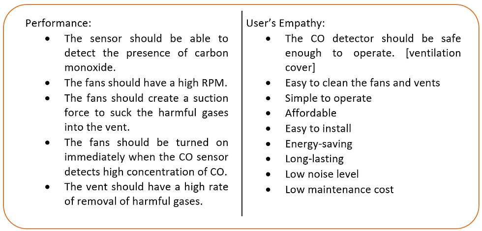
Figure 1: Performance and user empathy requirements
We then created an overall function structure diagram of a CO Detection System to understand how many inputs and outs our system will eventually have and this is shown in the figure below:
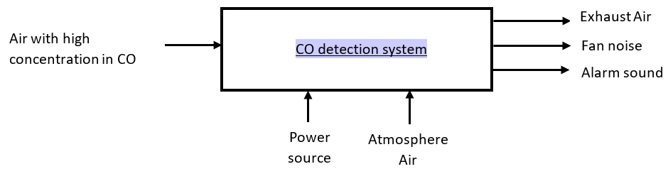
Figure 2: Overall function structure diagram of CO detection system
Not long after, we created a more detailed and complex diagram of the CO Detection System as shown in the figure below:

Figure 3: Detailed function structure diagram of CO detection system
b. Role Allocation
CEO: Chief Executive Officer
CFO: Chief Financial Officer
COO: Chief Operating Officer
CSO: Chief Safety Officer

Figure 4: Role allocation
c. Project Execution
i. Morphological Chart:
We collated a list of different materials we could use and strategically combined a variety of them to create 5 possible concepts for our prototype which can be seen below:

Figure 5: Morphological chart
ii. Concept Sketches:
We then sketched out each individual concept to visualise how our prototype could look in the end. Credits to Diana for being our artist with the best drawing skills in the class. The 5 sketches of our concepts can be seen below.
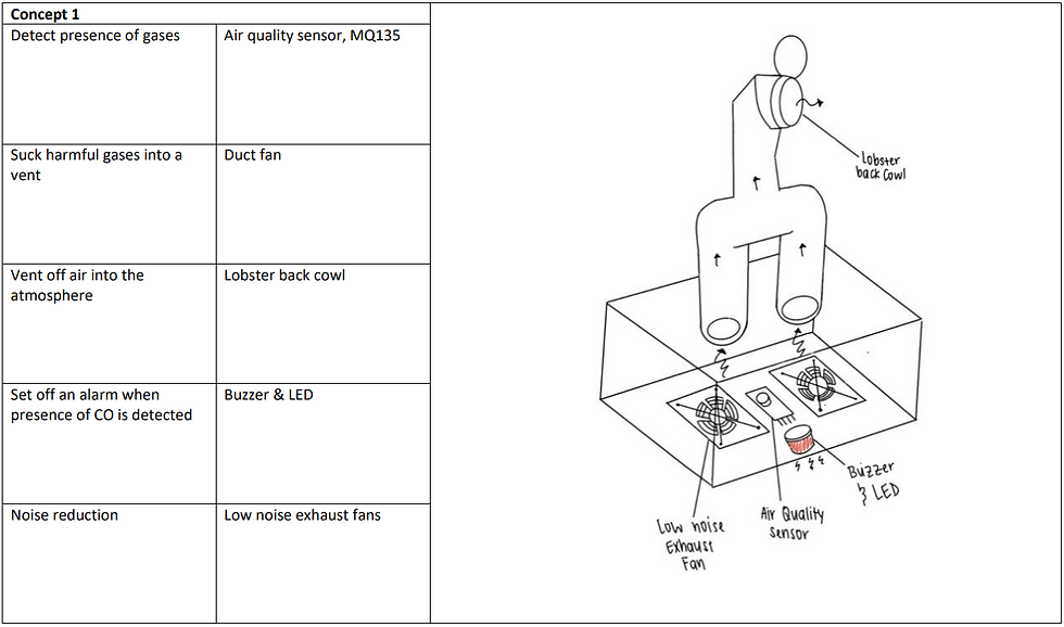
Figure 6: Sketch of concept 1
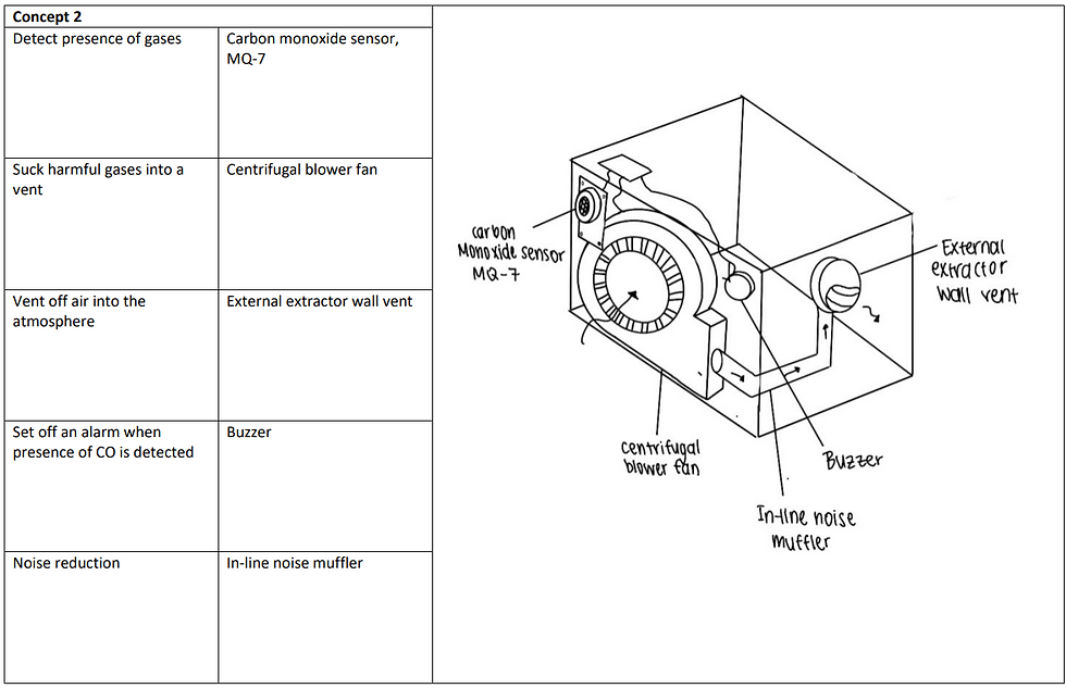
Figure 7: Sketch of concept 2

Figure 8: Sketch of concept 3

Figure 9: Sketch of concept 4

Figure 10: Sketch of concept 5
iii. Concept Evaluation Matrix
We then moved on to conducting the COW's matrix on our concepts based on the primary needs of the CO Detection System. We concluded that concept 4 was going to be built as our prototype as it scored the highest amongst all other concepts in the matrix which can be seen below.

Figure 11: Concept evaluation matrix
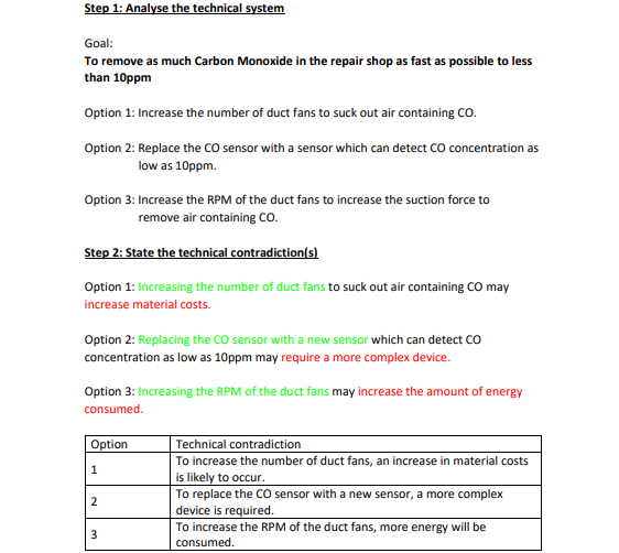
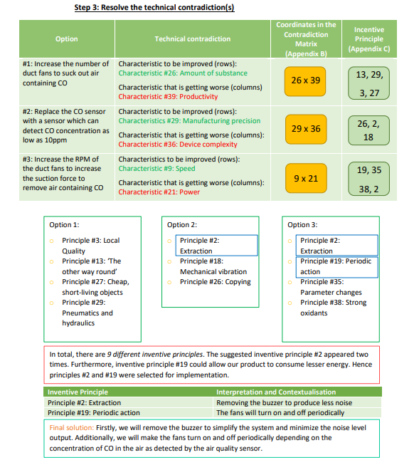
iv. TRIZ
v. Newly revised concept

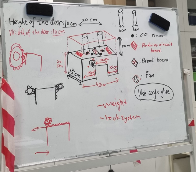
Figure 12: Old concept v1 Figure 13: Old concept v12
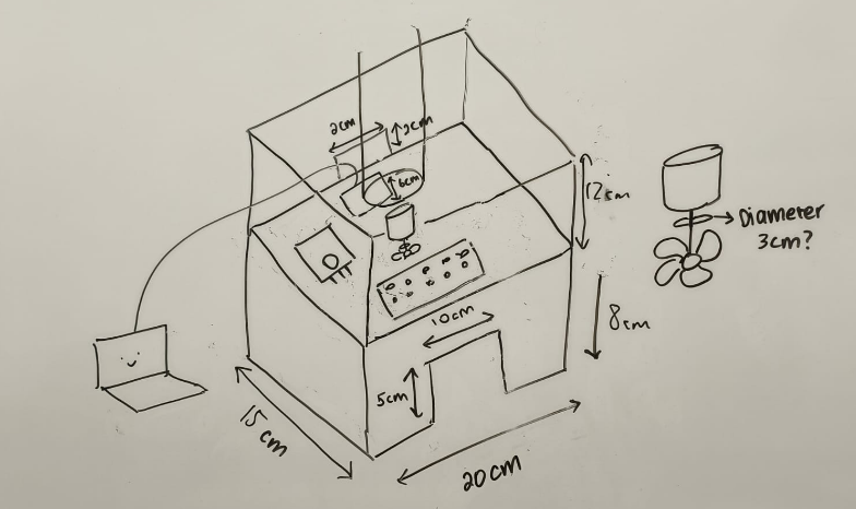
Figure 14: Finalised concept
From our Triz, we concluded that we should in fact remove the buzzer feature from our concept as it adds unwanted noise in Redza's car repair shop which is already noisy enough from all engine and tool noises. Furthermore, the module coordinator only provided each group with one piece of acrylic sheet which was 800mm by 420mm. This didn't allow our prototype to hold 2 Arduino kits inside. Hence our coach, Mr Chua, recommended us to scale down our prototype even further. Hence instead of including 2 fans in our prototype, we are only going to include 1.
vi. BOM Table
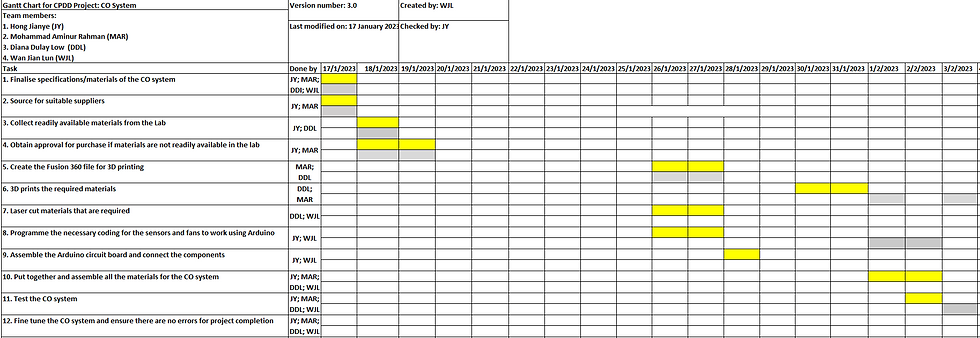
vii. Gannt Chart

3. Design and Build Process
Cardboard Prototyping [My Individual Contribution]
Initially, we weren't even meant to create a cardboard prototype in the first place. However, on 1st February, when I was meant to go to the lab to start 3D printing some of our components, all the 3D printers were already occupied by 8.15 am.
So instead of playing around and wasting time in the workshop, I grabbed a piece of cardboard and started visualising how our prototype will look like when we use the acrylic sheet. This was also very helpful because now I was able to physically visualise the exact dimensions our acrylic sheets need to be during laser cutting.
I used Figure 14 which we drew during class to first understand the basic dimensions of our prototype. I then referred back to the dimensions of the acrylic sheet we had which was 800mm by 420mm. I also referred back to Figure 15 which Jian Lun helped draw for us to roughly know how many pieces I should be cutting and where they will end up when hot glueing the cardboard pieces together.
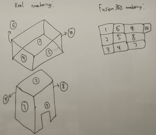
Figure 15: Prototype piece allocation
Here are a few pictures my friends took of me while I was cutting and assembling the cardboard. I don't really have that many since this wasn't a planned activity we had:

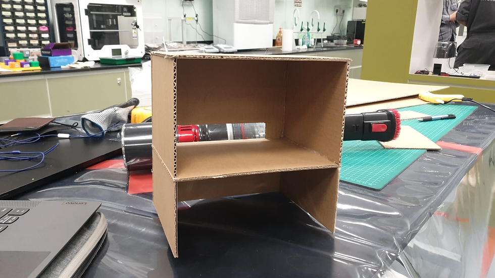
Figure 16: Scrap parts Figure 17: Cardboard prototype after glueing
I then measured the size of the components that need to protrude out of our bottom ceiling which were the LED, motor and MQ2 gas sensor using a digital vernier calliper.

Figure 18: Dimensions of holes required in the bottom ceiling
This is what the cardboard prototype looks like after cutting out all the holes:
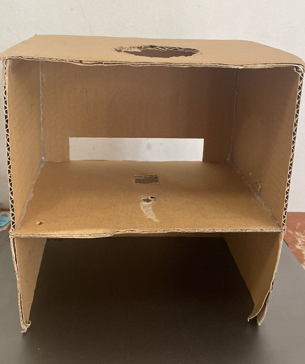
Figure 19: Cardboard prototype after a few weeks
Arduino Coding [Diana]
Link to Diana's Blog: https://cp5070-2022-2b01-group4-diana.blogspot.com/
Diana was an absolute legend when we had to start coding. I recall the night before, I was attempting to create the code in the comfort of my house. However, it was to no avail. So I guess I'll let Diana explain in her blog about her thinking process when she was creating the code.
The finalised code is shown below:
#define ledPin 6
#define sensorPin A0
void setup() { Serial.begin(9600); pinMode(3,OUTPUT); pinMode(ledPin, OUTPUT); digitalWrite(ledPin, HIGH); } void loop() { Serial.print("Analog output: "); Serial.println(readSensor()); delay(500); } int readSensor() { unsigned int sensorValue = analogRead(sensorPin); unsigned int outputValue = map(sensorValue, 0, 1023, 0, 255); if (outputValue > 50) { analogWrite(ledPin, outputValue); analogWrite(3,50); delay(1000); } else digitalWrite(ledPin, LOW); return outputValue; }
Cardboard Working Prototype [Group]
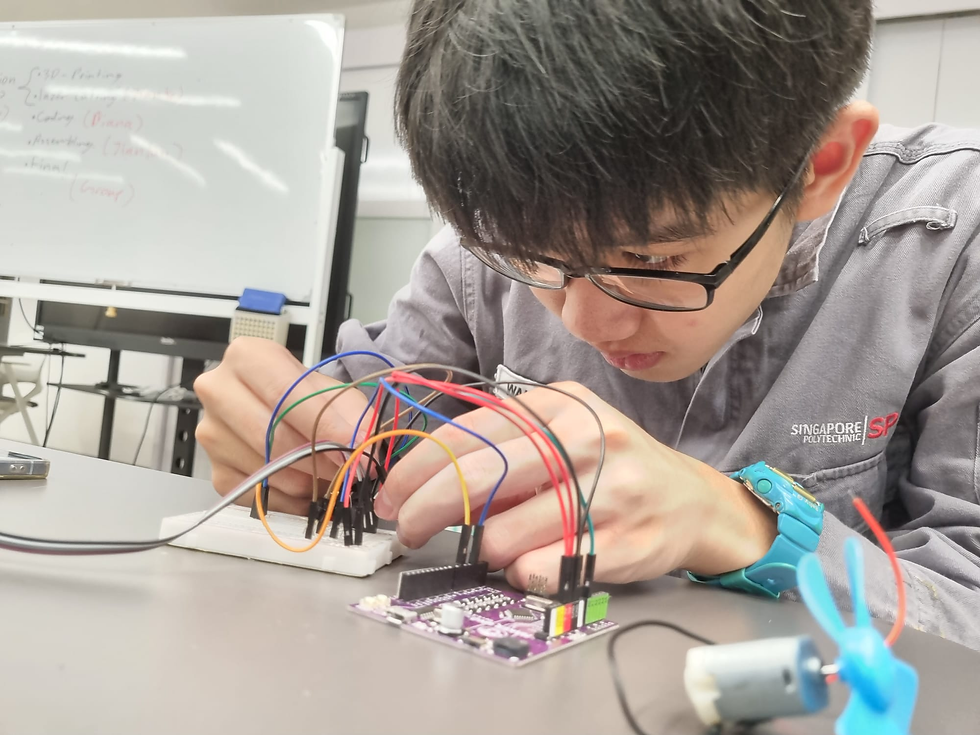
Once Diana completed the code in the lab, we immediately assembled the prototype and the video below shows it in working conditions.
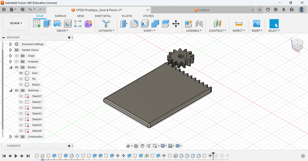
Fusion 360 [My Individual Contribution]
This is going to be a long one, so I'll just state the individual steps I took to create a fusion file for our Rack & Pinion, Door and vent.
Rack & Pinion + Door:
1. Click on Modify and select "Change Parameters"
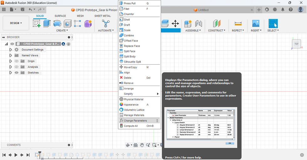
2. Insert the following parameters for future purposes

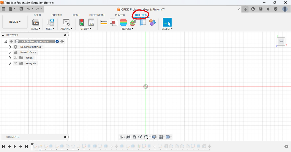
3. Click on the Utilities Tab
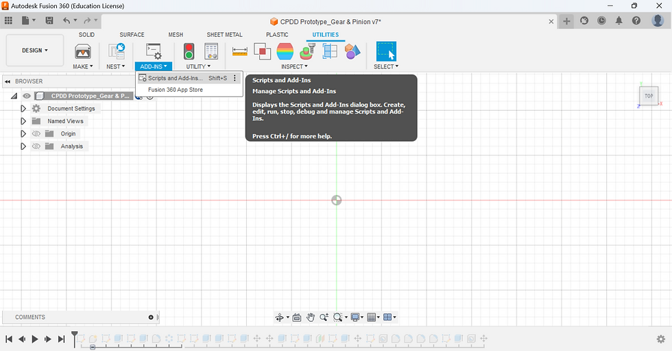
4. Click on ADD-INNS, then select Scripts and Add-ins
5. Select "SpurGear"

6. Insert the gear parameters as mentioned in step 2

7. Click "OK"

8. Add construction lines down the sketch

9. Draw a borderline for the teeth on the rack
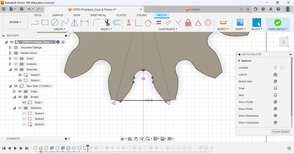
10. Offset the rack teeth to create a shape like this

11. Insert another sketch of a rectangular segment to a length of your liking
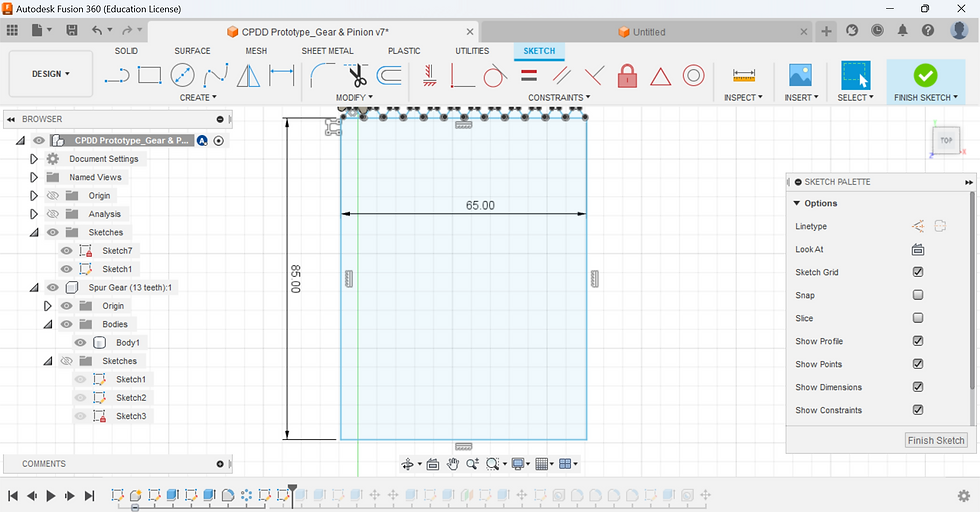
12. Duplicate the teeth across the entire length of the rectangular segment.
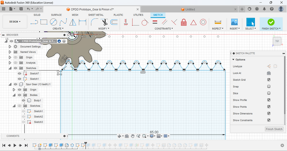
13. Extrude the Rack to be the same width as the Gear.
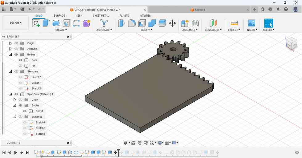
14: Create a sketch on the gear to make a rod stick out of the gear

15. Extrude by 10mm

16. Fillet the sides of the door to create a smooth surface
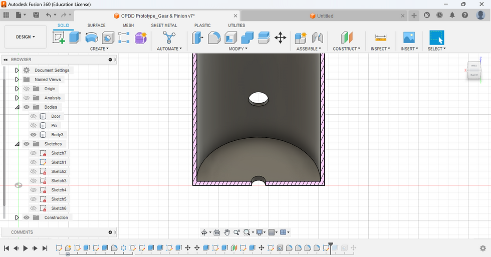
Vent
1. Create a circular sketch of 62mm in diamter and offset it by 2mm

2. Extrude the sketch by 150mm

3. Create a hole of 10mm which is 30mm above the base of the cylinder

4. Sketch another circle with a diameter of 7mm in the middle of all the other sketches

5. Extrude it by 3mm to create a base with a small hole in the middle
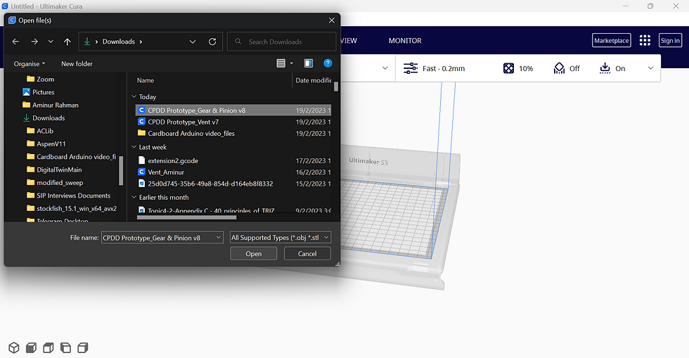
3D Printing [My Individual Contribution]
1. Click on the file option on the top left and select "Export.."

2. Change the file type to .stl and Export
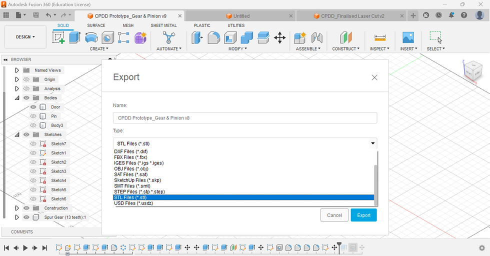
3. Repeat steps 1 and 2 for the Vent

4. Insert a thumb drive to your laptop

5. Open Cura and select the 3D printer you will be using
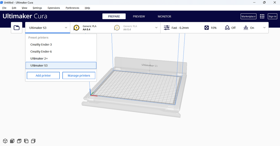
6. Click on the file option in the top left corner and select the .stl you want to print
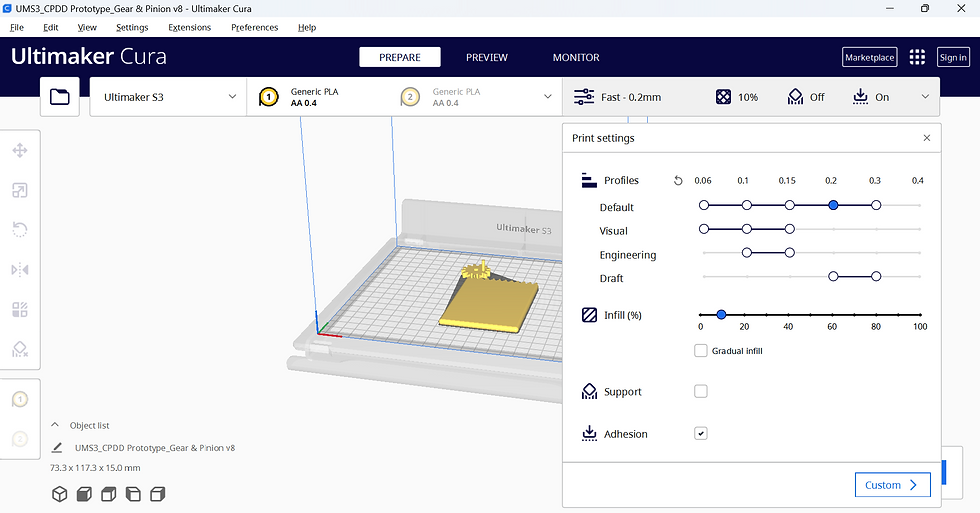
7. Adjust the setting to your liking. I will be setting the profile to 0.2 and infill as 10%
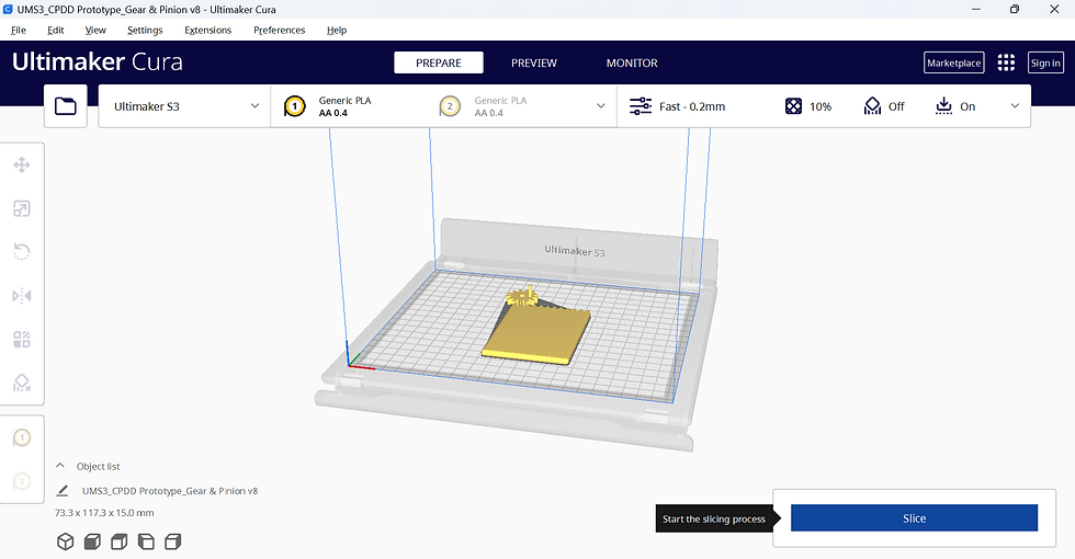
8. Slice your file
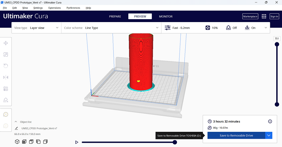
9. Save to Removable Drive

10. Repeat steps 6 to 9 for the Vent
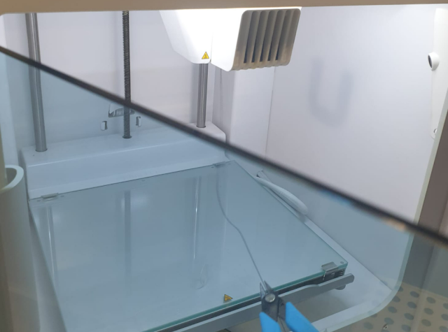
In case you are required to set up an Ultimaker S3 by yourself, I'll give a quick tutorial.
1. Turn on the main power supply
2. Turn on the Ultimaker by flicking the switch behind
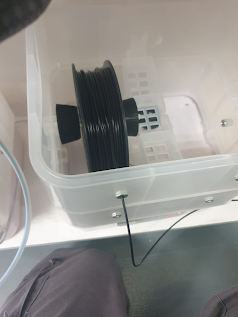
3. Load the Filament roller onto the tray which is located below the Ultimaker and ensure the box is showing temperature values on the front.
4. Unlock the filament inserting hole by flicking the knob up and inserting the filament. once the filament has been inserted into Ultimaker, flick the knob down to secure the filament.


5. Click the "load" option on the screen to load the filament into the printer head
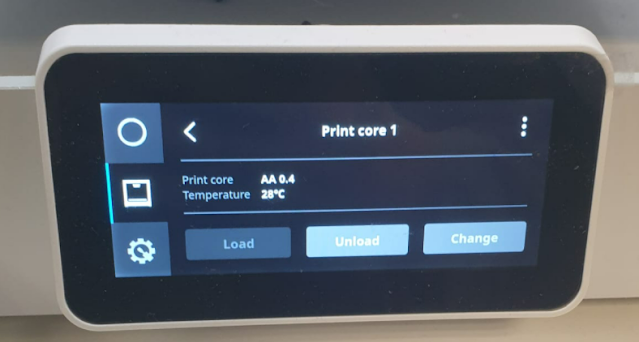
6. Allow the filament to come out of the print core until it touches the base of the printer. Then use a set of tweezers to cut off the filament.
7. Tap on Confirm once you cut off the excess filament which extruded out of the print core.

8. We can now select the file to print from the home page

Laser Cutting [Jianye]
Link to Jianye's Blog: https://hongjianye0822.wixsite.com/cp5070-2022-2b01-gro
Integration of All Parts [Jian Lun]
Link to Jian Lun's Blog: https://cp5070-2022-2b01-group4-jianlun.blogspot.com/
Final Working Prototype Video [Group]
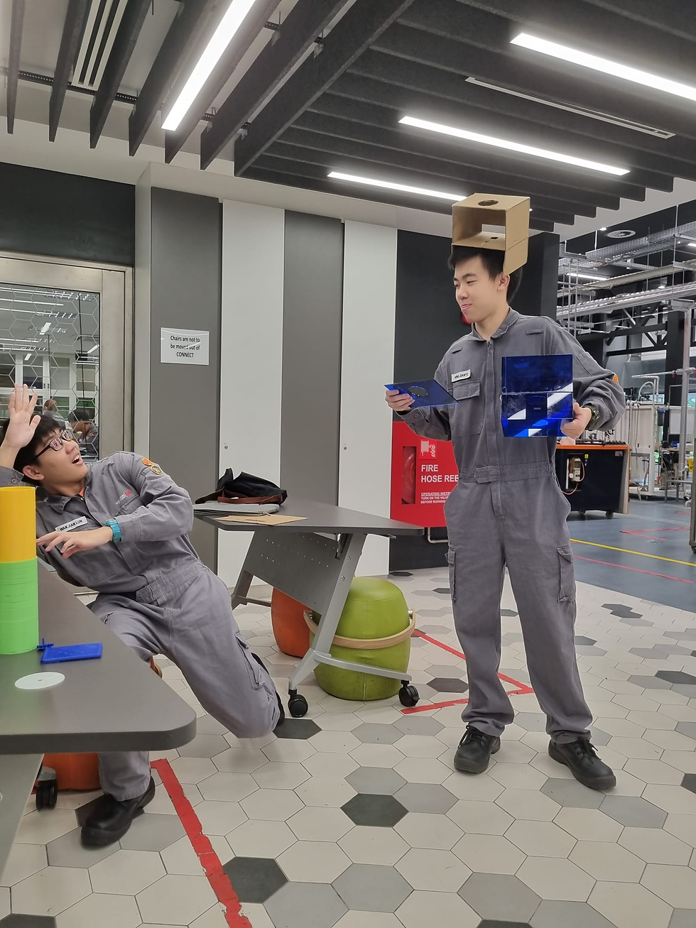
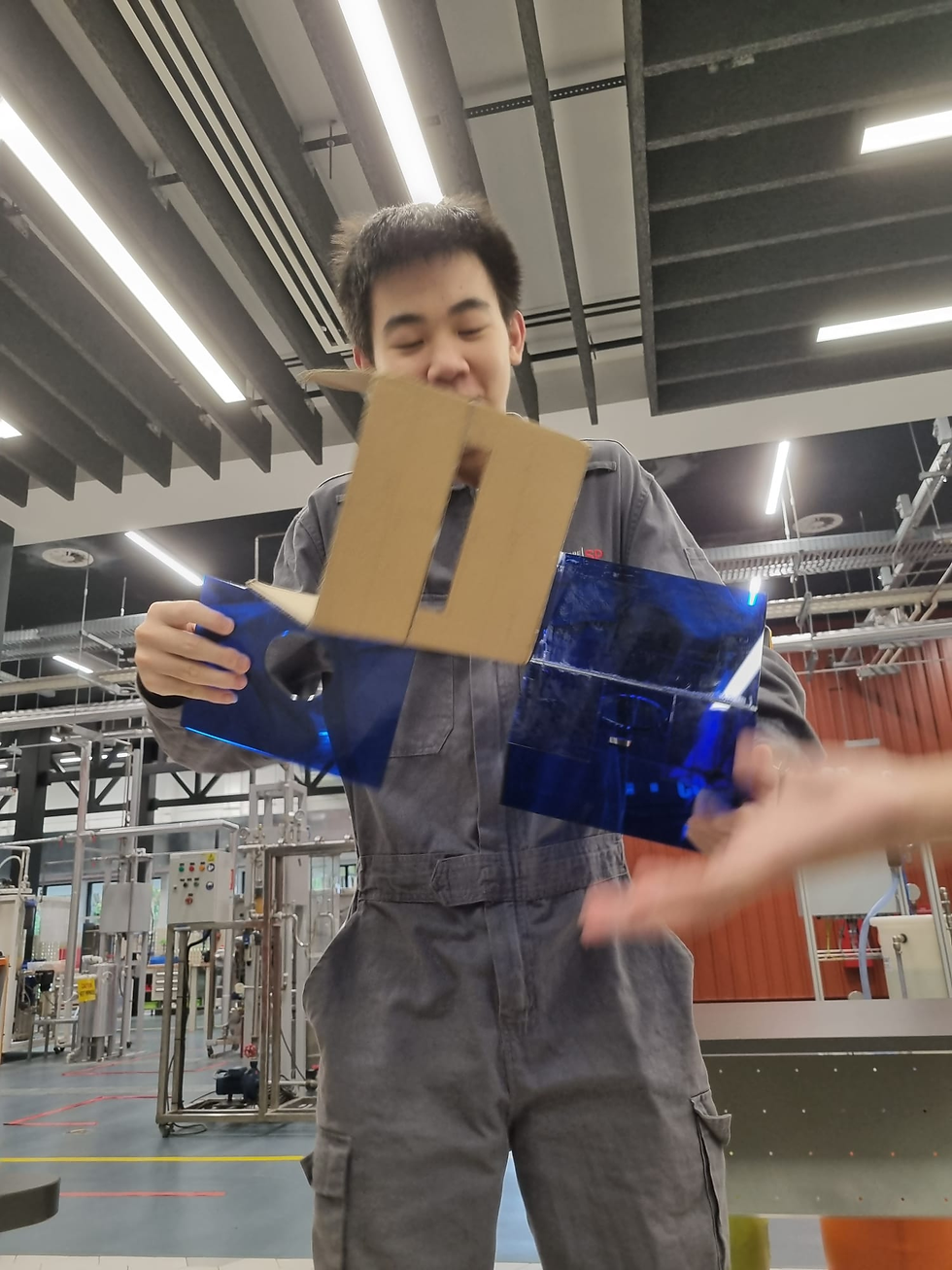
Hero Shots


4. Problems & Solutions
Problem 1: Wires getting tangled up during the final assembling stage
We required a large number of wires to connect the breadboard to various components, such as the LED and motor, and during the final assembly, these wires often got tangled. To overcome this challenge, we had to rearrange the positioning of the breadboard and Arduino kit to create more space, allowing us to separate each component more effectively.
Problem 2: Fusion format for laser cutting
Initially, our fusion file for laser cutting didn't contains that many gaps in between each piece we planned to laser cut as shown in the picture below:
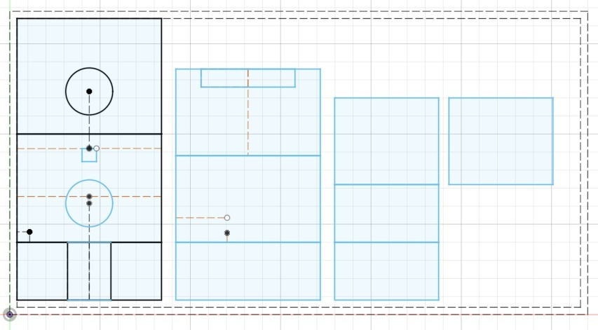
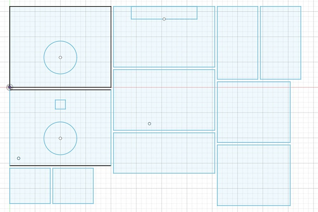
We consulted our peers such as Valerie and Asraf from class 05 as they had past experiences using the laser cutting machine before and they were very helpful indeed. They recommended including a small gap, around 2mm, per piece we are going to laser cut. This was because if we didn't include spacings in between each individual piece, their final sizes may end up being smaller than we expected. They even helped me out by sharing a unique software called Inskape to manoeuvre them more easily. However, since I was quite inexperienced with Inskape, I just adjusted the spacing between our pieces in fusion. The final fusion file which we used for laser cutting is shown below:
3D printing errors which led to components not fitting
In our very first 3D prints, I experienced a lot of problems with the printer which I was working with. The outside of our cylinder vent had black marks on it and the inner PLA materials weren't holding up very well as can be seen in the following picture.
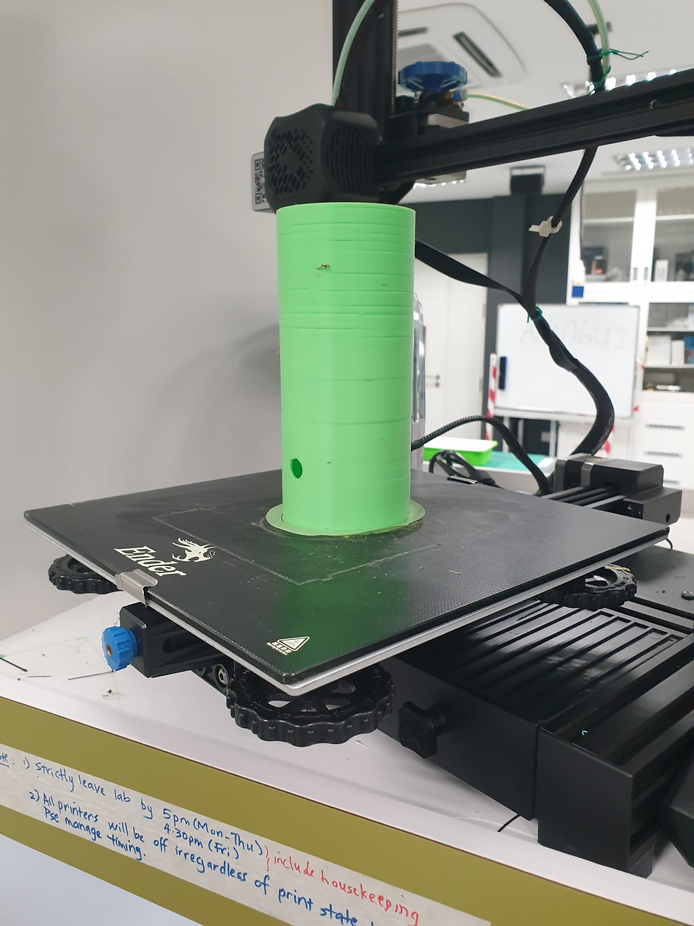
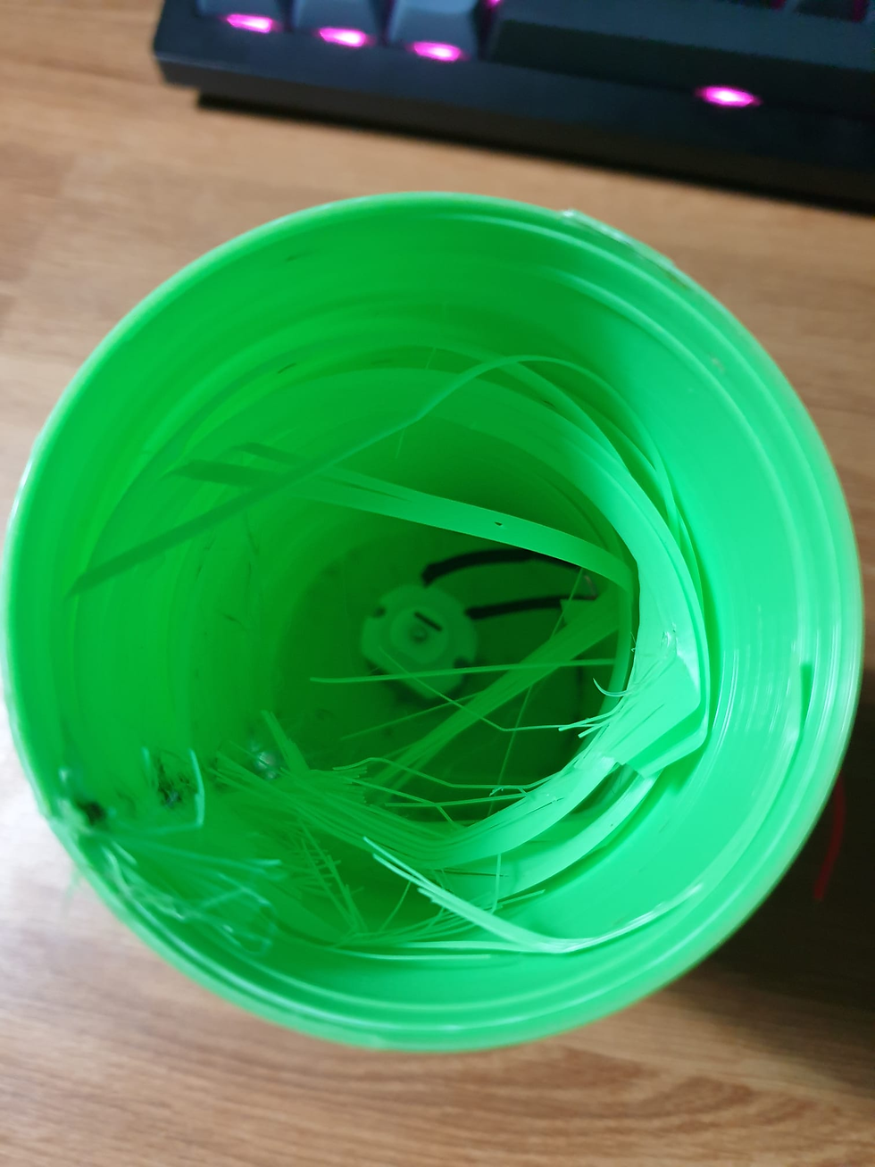
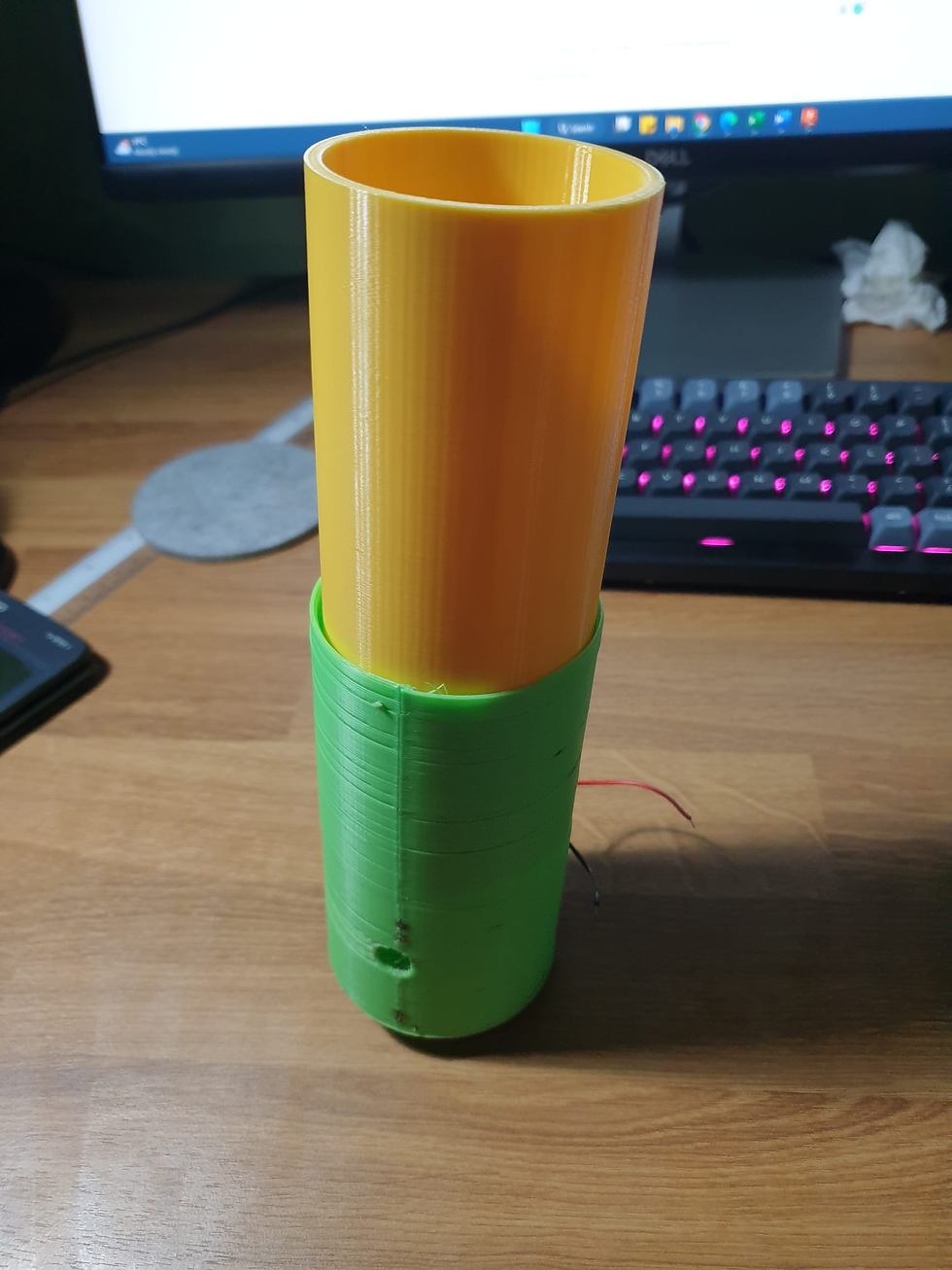
After noticing the same issues occurring for my peers who used the same printer, I concluded that the rubber tip at the nozzle head had melted and was interfering with the PLA extruding from the nozzle while printing. This also caused the vent to not fit through the holes on our acrylic sheets. Hence I suggested that we cut out the top portion of the faulty vent and attach a smaller vent above it. This way, we can still reuse a failed 3D print while still meeting one of the criteria for our CO Detection System. The final vent now looks like this:
Acrylic glue took a longer time to dry than expected
On our first day of attempting to use acrylic glue to combine our acrylic pieces together, Jianye and I realised that we were taking five to ten times longer for our glue to dry as compared to our classmate Enzo who only took two to three minutes to dry. However, we did learn that placing the blower very close to the area where the acrylic glue was made it dry faster.
Hence on the second day, Jianye and I reapplied what we had learnt and started glueing out acrylic pieces together but with a different set of acrylic glue. To our surprise, the glue dried up within two to three minutes just like what our peers had mentioned. We concluded that there was a very high possibility that the glue we initially used was either exposed to water. This increased the volume of liquid in the small bottle of acrylic glue, however, this caused it to lose some of its properties to melt acrylic and dry quickly.
5. Project Design Files as Downloadable Files
6. Learning Reflection
In the beginning, I think that this final project has encompassed all the skills that we learned from ICPD and CPDD. We applied the core skills that we acquired, including digital modelling with Fusion 360, 3D printing, laser cutting with a laser cutting machine, and using gears for mechanisms, making this a very long and tedious yet rewarding challenge.
This project also taught me the value of teamwork, as it allowed us to complete the task efficiently. We divided the workload evenly, leveraging each other's strengths. For instance, Jian Lun and Diana are proficient in programming and Arduino, so they handled the coding aspect. Jianye and I concentrated on 3D printing and laser cutting, as well as integrating acrylic sheets with acrylic glue. This enabled us to execute our plan seamlessly because we all worked in our comfort zone.
As the adage goes, "every man is a piece of the continent, a part of the main." We brainstormed together to generate more ideas, and due to limited access to the acrylic sheet, we had to reduce our prototype's size and make essential adjustments to our dimensions. Hence, we reduced the number of fans and Arduino kits in our prototype but we were still able to meet the objective of the system.
This journey taught me several valuable troubleshooting skills that I can apply in the future. During 3D printing, I discovered that one of the EnderCreality printers was printing out black-coloured filament which looked burnt. I tried my best to clean the nozzle head, but in the process, I discovered that the rubber coating on the nozzle head had actually melted and I informed Ms Serene immediately. I also learnt how to conduct maintenance on Ultimaker S3 when it isn't extruding any filament from the print nozzle.
Overall, I feel fortunate to have collaborated with my amazing teammates on this project for several weeks. I somewhat enjoyed the process and hope to implement the skills I've gained into my capstone project in year 3.


Comments